MSA 2 -- Measurement System Analysis Method 2
The MSA Method 2 (also known as Procedure 2 or Gage R&R Study) is the most comprehensive method of measurement system analysis. It evaluates the repeatability and reproducibility of a measurement system while considering multiple appraisers and multiple parts.
Overview
Purpose and Application
MSA 2 answers the question: How large is the proportion of measurement variation in total variation -- and where does this variation originate?
While MSA 1 only considers the repeat precision of a single appraiser on a single part, MSA 2 examines the complete measurement system consisting of:
- Measurement Equipment (Equipment Variation, EV)
- Appraisers (Appraiser Variation, AV)
- Interaction between appraiser and part (Interaction)
Experimental Designs
my8data supports two different experimental designs for MSA 2:
Crossed Design
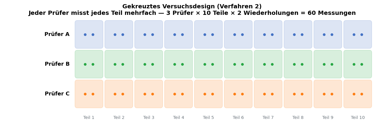
In the crossed design, each appraiser measures each part multiple times. This is the standard design and is recommended in most cases.
| Part 1 | Part 2 | Part 3 | ... | Part n | |
|---|---|---|---|---|---|
| Appraiser A | x Measurements | x Measurements | x Measurements | ... | x Measurements |
| Appraiser B | x Measurements | x Measurements | x Measurements | ... | x Measurements |
| Appraiser C | x Measurements | x Measurements | x Measurements | ... | x Measurements |
Typical Configuration: 3 appraisers, 10 parts, 2-3 repetitions = 60 to 90 measurements.
Tip: The crossed design provides the most complete information, as interactions between appraiser and part can be detected.
Nested Design
In the nested design, each appraiser measures different, separate parts. The parts are thus not measured by all appraisers.
| Parts 1-3 | Parts 4-6 | Parts 7-9 | |
|---|---|---|---|
| Appraiser A | x Measurements | -- | -- |
| Appraiser B | -- | x Measurements | -- |
| Appraiser C | -- | -- | x Measurements |
Use cases for nested design:
- Destructive Testing -- When the part is destroyed during measurement
- Consumptive Testing -- When the part is not available after measurement
- Large Parts -- When transport between appraisers is not practical
Important: With the nested design, interactions between appraiser and part cannot be calculated, since no appraiser measures the same part. The validity is therefore somewhat limited.
Typical Workflow
- Select experimental design (crossed or nested)
- Determine number of appraisers, parts, and repetitions
- Enter tolerance limits
- Perform measurements and enter measurement values
- Start calculation
- Evaluate ANOVA results and key figures
Input
Configure Experimental Design
Before data entry, set the experimental parameters:
| Parameter | Description | Recommendation |
|---|---|---|
| Design Type | Crossed or Nested | Crossed, if possible |
| Number of Appraisers | How many different appraisers perform measurements | At least 2, recommended 3 |
| Number of Parts | How many different parts are measured | At least 5, recommended 10 |
| Number of Repetitions | How often each appraiser measures each part | At least 2, recommended 3 |
| Upper Tolerance Limit (UTL) | Upper specification limit | According to drawing/specification |
| Lower Tolerance Limit (LTL) | Lower specification limit | According to drawing/specification |
Enter Measurement Values
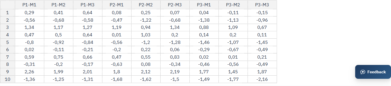
The input table automatically adapts to the selected configuration:
- Columns represent the individual parts
- Rows are grouped by appraisers, with repetitions as sub-rows
Tip: In the crossed design, ensure that appraisers measure the parts in random order and are unaware of the measurement values of other appraisers. This is critical for the validity of the results.
Info: You can name appraisers and part numbers individually. By default, appraisers are labeled as "Appraiser A, B, C, ..." and parts as "Part 1, 2, 3, ...".
ANOVA
ANOVA (Analysis of Variance) is the statistical core procedure of MSA 2. It decomposes total variation into its individual components.
ANOVA Table
After calculation, my8data displays the complete ANOVA table:
| Source | df | SS | MS | F-Value | p-Value |
|---|---|---|---|---|---|
| Parts | n-1 | SS_Parts | MS_Parts | F_Parts | p_Parts |
| Operators | k-1 | SS_Operators | MS_Operators | F_Operators | p_Operators |
| Interaction | (n-1)(k-1) | SS_Interaction | MS_Interaction | F_Interaction | p_Interaction |
| Repeatability | nk(r-1) | SS_Repeat | MS_Repeat | -- | -- |
| Total | nkr-1 | SS_Total | -- | -- | -- |
Legend:
- df = Degrees of freedom
- SS = Sum of squares
- MS = Mean square
- F-Value = Test statistic of the F-test
- p-Value = Significance level
Interpretation of ANOVA
The ANOVA helps you answer the following questions:
Is appraiser variability significant? If the p-value for "Operators" is less than 0.05, appraisers differ significantly from each other. Measures: Training, standardized work instructions.
Is there a significant interaction? If the p-value for "Interaction" is less than 0.05, certain appraisers measure certain parts systematically differently. This may indicate different measurement techniques.
Is part variation sufficient? The parts should show distinct variation so that the study is meaningful. Ideally, the parts should cover at least 80% of the tolerance.
Info: If the interaction is not significant (p > 0.25), it is automatically included in the repeatability (pooled model). This increases the accuracy of the remaining estimates.

Diagrams
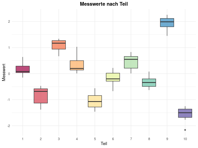
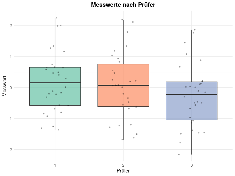
For graphical evaluation, my8data provides three diagrams:
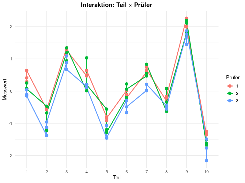
Interaction Plot (Part × Appraiser) — shows whether appraisers measure individual parts systematically differently (lines that are not parallel indicate an interaction).
Measurement Values by Part — variation of measurements per part; makes part-to-part variation visible.
Measurement Values by Appraiser — variation of measurements per appraiser; makes differences between appraisers visible.
Key Figures
The following key figures are derived from the ANOVA:
Variance Components
| Key Figure | Abbreviation | Description |
|---|---|---|
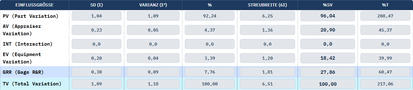
| Equipment Variation | EV | Variation caused by the measurement equipment (repeatability). Portion of measurement variation attributable to the measurement equipment itself. |
| Appraiser Variation | AV | Variation caused by appraisers (reproducibility). Portion of measurement variation resulting from different appraisers. |
| Gage R&R | GRR | Total measurement equipment variation (EV + AV). Combination of repeatability and reproducibility. |
| Part Variation | PV | Variation of parts. Represents the actual variation of the measured parts. |
| Total Variation | TV | Total variation (GRR + PV). |
Percentage Shares
The key figures are presented as percentage shares relative to tolerance (%Tolerance) and relative to total variation (%Contribution):
| Key Figure | Acceptable (green) | Marginal (yellow) | Not Acceptable (red) |
|---|---|---|---|
| %GRR (Tolerance) | <= 10 % | 10 % -- 30 % | > 30 % |
| %GRR (Contribution) | <= 1 % | 1 % -- 9 % | > 9 % |
| %EV | Small proportion of GRR | -- | Dominates GRR |
| %AV | Small proportion of GRR | -- | Dominates GRR |
Number of Distinct Categories (ndc)
The ndc value indicates how many distinguishable categories the measurement system can differentiate within the process variation.
| ndc | Assessment |
|---|---|
| >= 5 | The measurement system can resolve the process sufficiently. |
| 3 -- 4 | Limited resolution. Usable for rough estimates. |
| < 3 | The measurement system is unsuitable. No meaningful distinctions can be made. |
Important: An ndc value less than 5 means the measurement system is unable to reliably distinguish good parts from bad parts. In this case, measures to improve the measurement system are urgently required.
Improvement Measures
Depending on whether EV or AV represents the larger proportion of GRR, the recommended measures differ:
| Problem Area | Possible Causes | Measures |
|---|---|---|
| EV Dominates (Equipment) | Wear, insufficient resolution, unsuitable measurement principle, environmental influences | Maintain/replace equipment, choose higher resolution, stabilize environmental conditions |
| AV Dominates (Appraisers) | Different measurement techniques, insufficient training, unclear instructions | Train appraisers, standardize measurement instructions, introduce fixtures |
| Significant Interaction | Appraiser-dependent handling of certain part geometries | Unify measurement technique, introduce fixtures |
Tip: Always consider both the percentage shares and the ndc value. A measurement system with %GRR just above 10% but ndc >= 5 may still be acceptable if additional organizational measures are implemented.
Overall Assessment of Measurement System
The "Measurement System Assessment" field summarizes the result in a single judgment. The assessment logic proceeds in two stages:
Stage 1 – %GRR (Tolerance):
| Assessment | Condition |
|---|---|
| capable | %GRR ≤ "capable up to" threshold (Standard: 10 %) |
| conditionally capable | %GRR ≤ "conditionally capable up to" threshold (Standard: 30 %) |
| not capable | %GRR > "conditionally capable up to" threshold |
Stage 2 – NDC (optional):
If the "ndc ≥" field contains a minimum value, the NDC is used as an additional criterion. Both conditions must then be met simultaneously (AND logic):
- %GRR threshold met and ndc ≥ minimum value → Assessment as per Stage 1
- ndc < minimum value → Assessment not capable, regardless of %GRR value
If the "ndc ≥" field is empty, the ndc does not affect the overall assessment – but it continues to be calculated and displayed.
Example: %GRR = 7.74 % (≤ 10 %, thus "capable") and ndc = 4, minimum ndc = 5 → Assessment not capable, because the ndc requirement is not met.